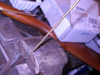
First I took a 1/8" rod and bent the end in a vise.

To make a hook like this.

So I could pull out the 600-102 piercing assembly...

Standard 38 style piercing pin and seal.

Somewhat worse for wear.

I forgot to take a clear picture of the tube cap. This one has a hole the end of the CO2 cartridge sits in.
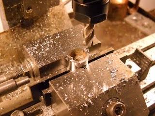
Since I had one valve front out I measured the screw slot and milled a cheap socket to fit.
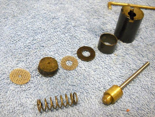
The front valve parts.

The feed arm. There's another setscrew under the first.
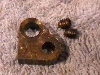
Much better shape than the other one.
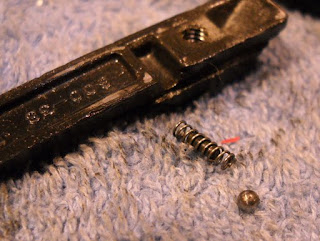
It also has the proper spring, ball and guide for the slide.

The guide is just a tiny dowel pin.
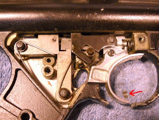
As you can see the trigger guard is broken. Also that tiny piece fell out when I removed the cover plate...
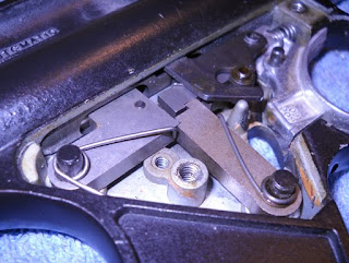
Some more gratuitous shots of the trigger mechanism.
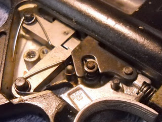
Notice that this trigger group has the stop and stop roller. I'm still not clear why these were added to the design (or were they removed from the design?)
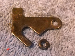
Stop and stop roller.

The link is the source of that small broken piece. Not sure how that would happen?

I left the ring in place when I removed the tube this time, made it much easier to remove.
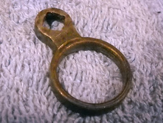
This ring is in better shape than the other. I'll pull a bunch of measurements off of it.
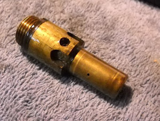
The rear valve body is made of brass on this one. See the small bleed hole on the side?

So the hammer is pushed back by gas coming from the off center hole in the end. When it reaches the bleed hole it's caught by the sear and the bleed hole bleeds off the gas inside the hammer? Sounds right.

Another view. Must have been fun to set up the screw machines to make these.
Now to think about what to do with two separate piles of malfunctioning 600 parts...
0 comments:
Post a Comment